


Measuring Instruments
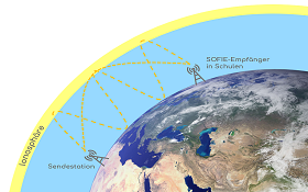
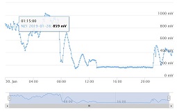
To record solar radio bursts the DLR_Project_Lab Neustrelitz in collaboration with the company Neuhein GbR developed a specific VLF receiver named SOFIE RX. For the participating schools, the receiver is tuned to different frequencies (cp. table below). The SOFIE RX of a school registers the signal strength of radio waves emitted by a powerful transmitter. Solar radio bursts (solar flares) are characterized by significant changes of the signal strength.
| Frequency | Transmitter | Location | ID |
| 22,1 kHz | Skelton | Great Britain | GQD |
| 23,4 kHz | Rhauderfehn | Germany | DHO38 |
| 24,0 kHz | Cutler | USA (Maine) | NAA |
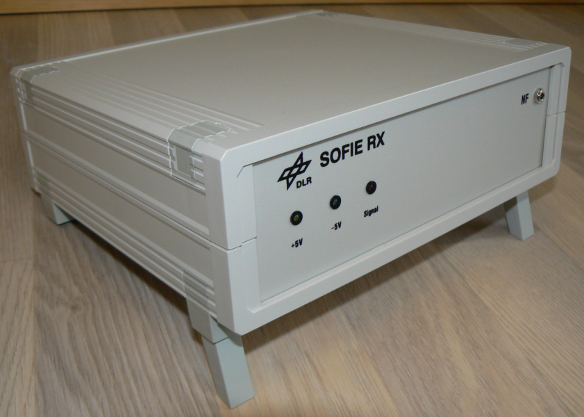
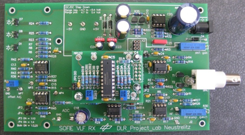
The Receiver
The installation of a SOFIE RX and the antenna requires only a power supply, an internet connection and an appropriate undisturbed location. Local interferences are caused, among other things, by a large number of electric devices, televisions or big receivers (for instance fire departments) in the surrounding of the receiver. These things emit background radiation that disturbs good reception which is why they should be located and if possible removed from the environment. The SOFIE receivers come with an integrated microcontroller, which automatically connects to the Internet and transfers the data to a server of the DLR_Project_Lab. The students can view, share, and edit the measuring data via a web portal. The SOFIE receiver does not require an additional computer.
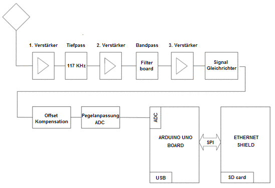
The lower right graphic shows how the SOFIE server works. The high frequency (HF) signals detected by the antenna are processed by a preamplifier before passing the filter. The filter is a variable unit and can easily be adjusted to various frequencies of interest. The narrow band filter provides the VLF signal for a selected frequency. After a level adjustment the data is sent to the web server and finally to the internet (web portal).
 |
 |
 |
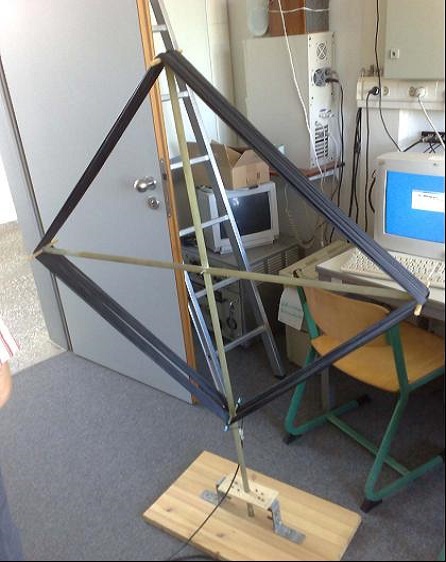
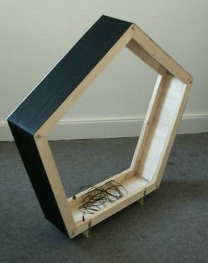
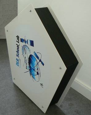
The Receiving Antenna
In order to record radio waves, the SOFIE receiver requires a loop antenna. It can be constructed with a small diameter (< 1 meter wide) and a large number of loops or with a larger diameter and fewer loops. However, keep in mind that a larger diameter of the antenna with less loops ensures a more accurate data record. (Example: 25 loops on a 2 meter frame are better than 50 loops on a 1 meter frame.) The antenna can be constructed from crossed bars, wood ledges or other non-conductive materials. The number of frame edges is not important. Figure 2 (left) illustrates a simple but effective quadratic antenna built by students. The antenna of the DLR_Project_Lab Neustrelitz (middle and right) is a pentagon with an edge length of 1 meter, wound by a 1.5 mm copper wire 75 times. The best location for the antenna would be on a roof or outside. However, the antenna must be protected from lightning strikes (which may cause damage). It is also possible to set up the antenna inside, close to a window. For optimal receiving conditions, the antenna must be carefully adjusted.
 |
 |
 |